Introduction:
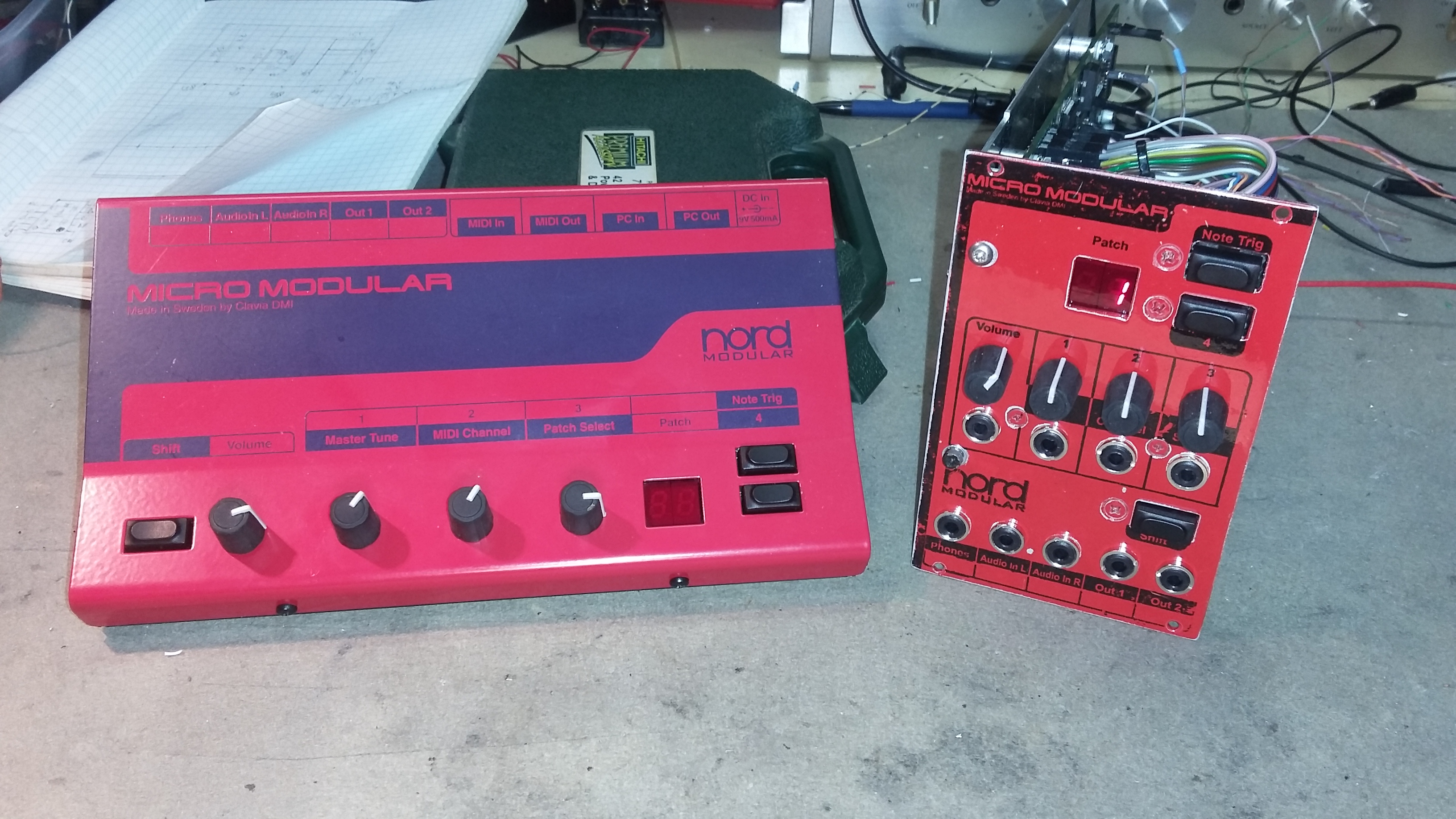
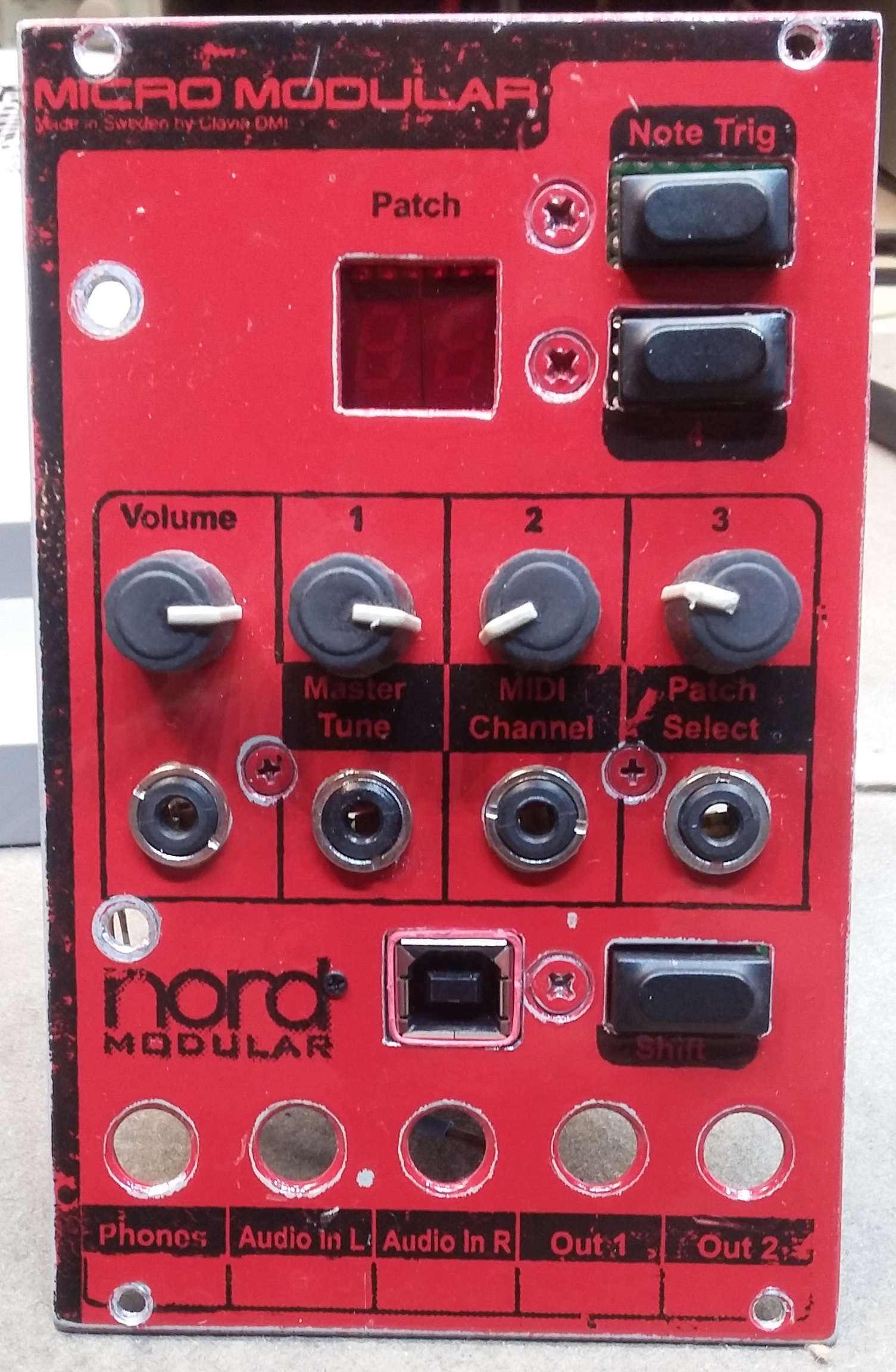
The Clavia Nord Micro Modular was introduced back in 1999 and is a small box that emulates a modular synthesizer by means of a Digital Signal Processor.
It is a reduced version of the Nord Modular; which ment just 4 voices and no multitimbrality. In a way, those limitations place it closer to a real modular system.
Over the years i have made hundreds of patches for making droning sounds that i use in making ambient music. The Micro Modular is like a paiters' pallette for
making sounds. Setting up a patch is done with an editor run on PC. The editor is graphical: One puts modules in order and 'connects' them up with virtual wires.
Patches can be saved to disk and in one of the 99 patch slots of the Micro Modular. If stored in the synth, one can call up the patches without the computer being
connected, so it's ideal for on stage use.
Now i found that the Micro Modular is often ideal to use with my real modular setup. And it got to live nearby. But how much better to have it integrated in the rack.
I had the idea for a while and when i found a scruffy looking unit for sale on an auction...

Auction bid won!
What's in the box?
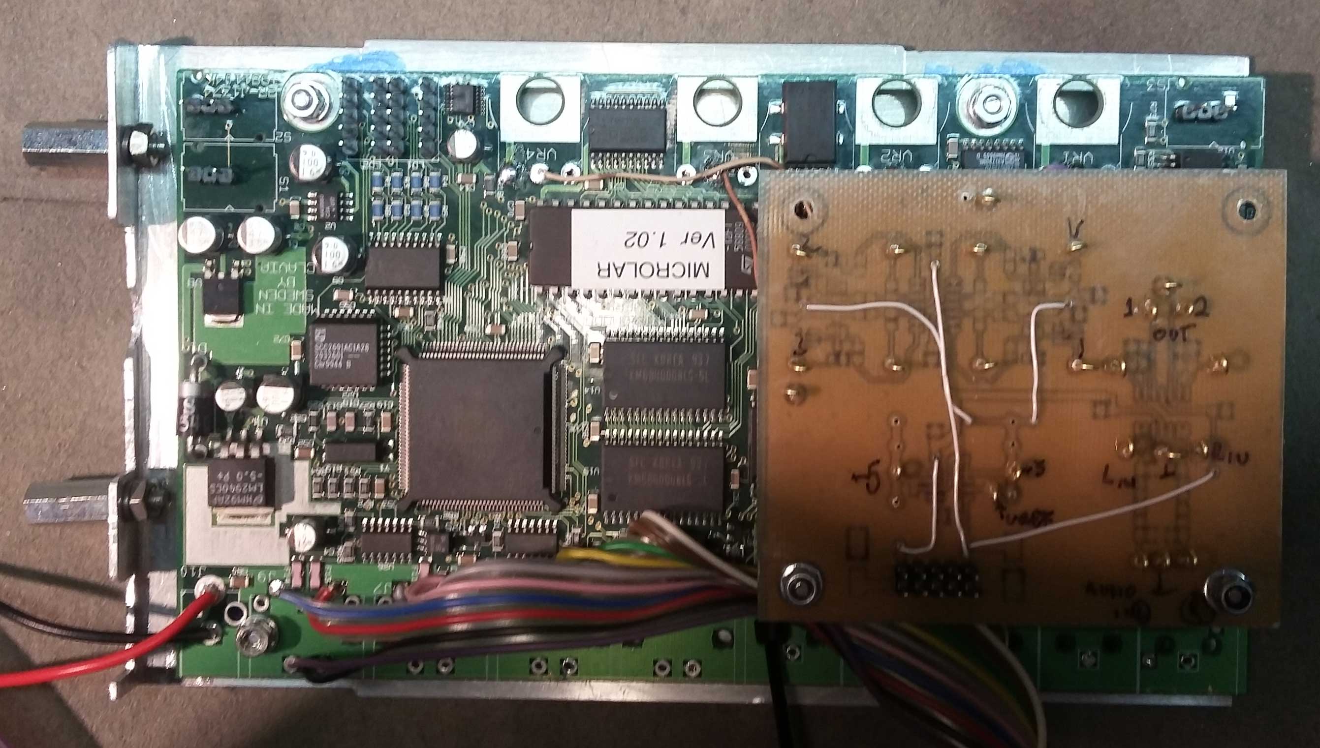
The Micro Modular is easy to open up. Pull off the four knobs and undo two screws on the front and two on the back. The read cap can be lifted to reveal a well made
PCB.
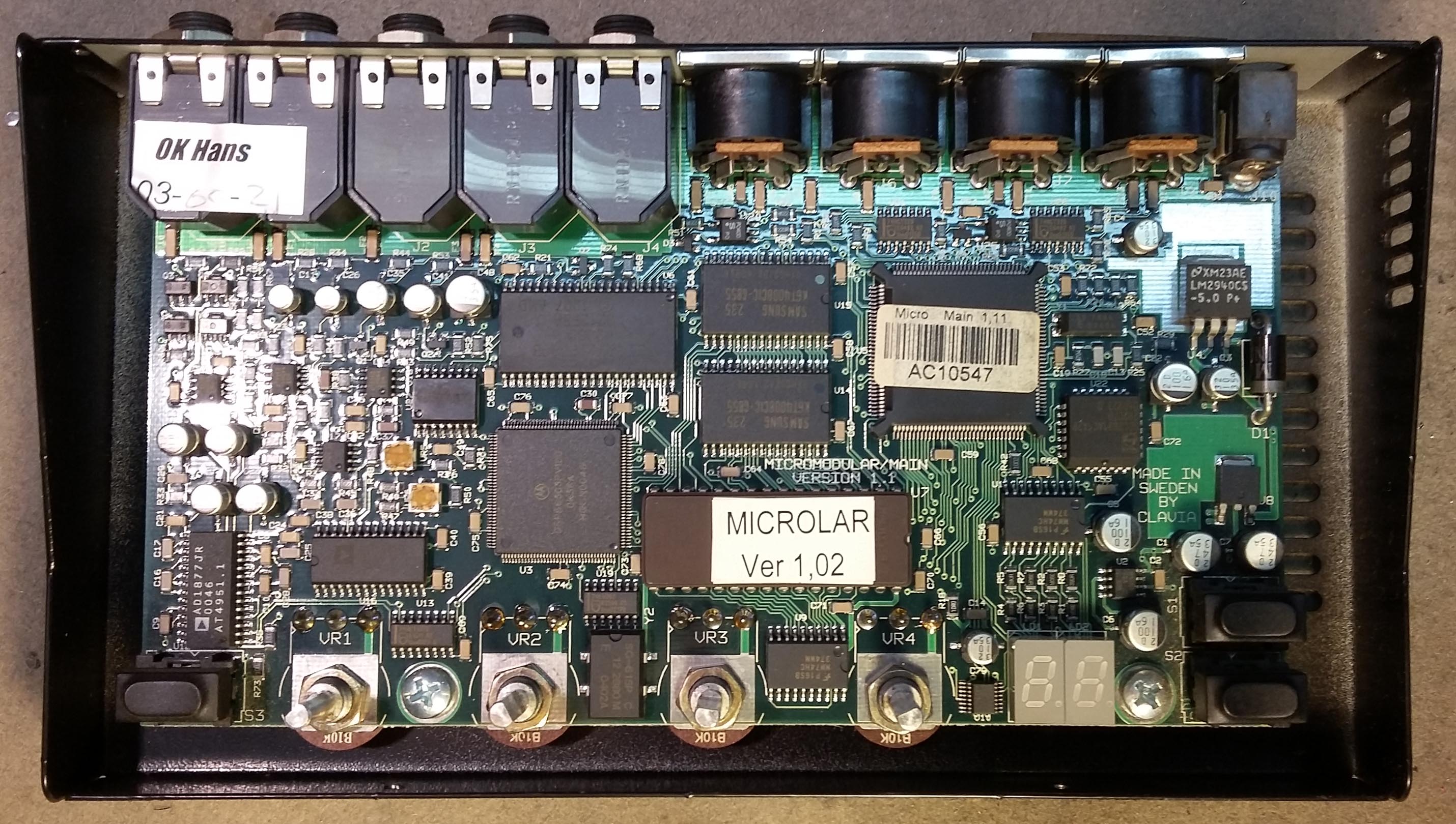
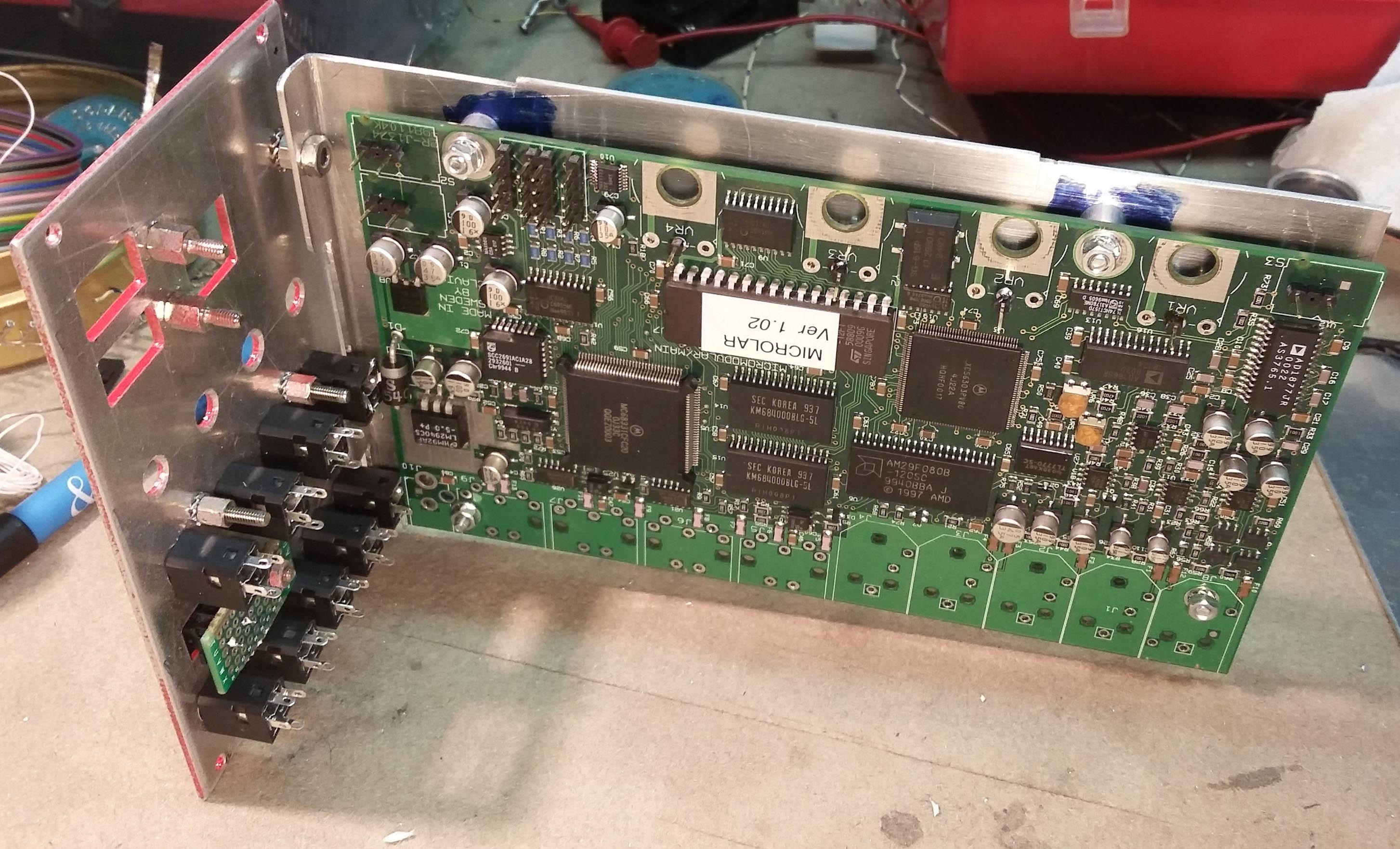
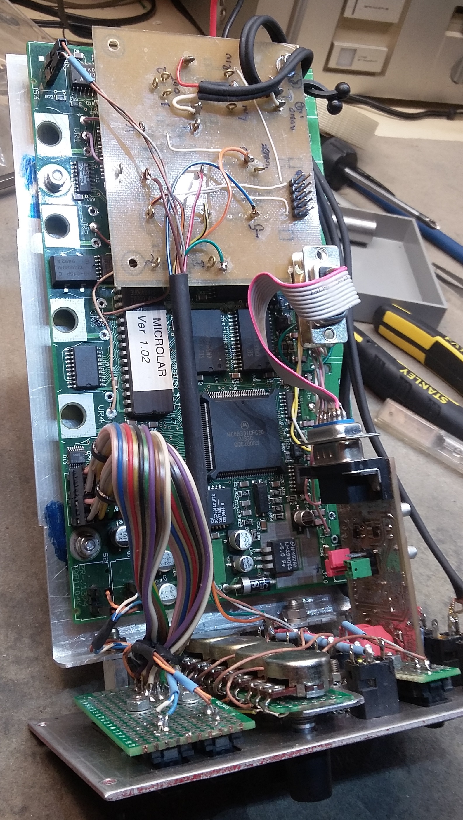
Inside the Micro Modular
In my Schroff industrial 19'' case, the 17cm depth allows the PCB to be mounted to run backward from the face plate.
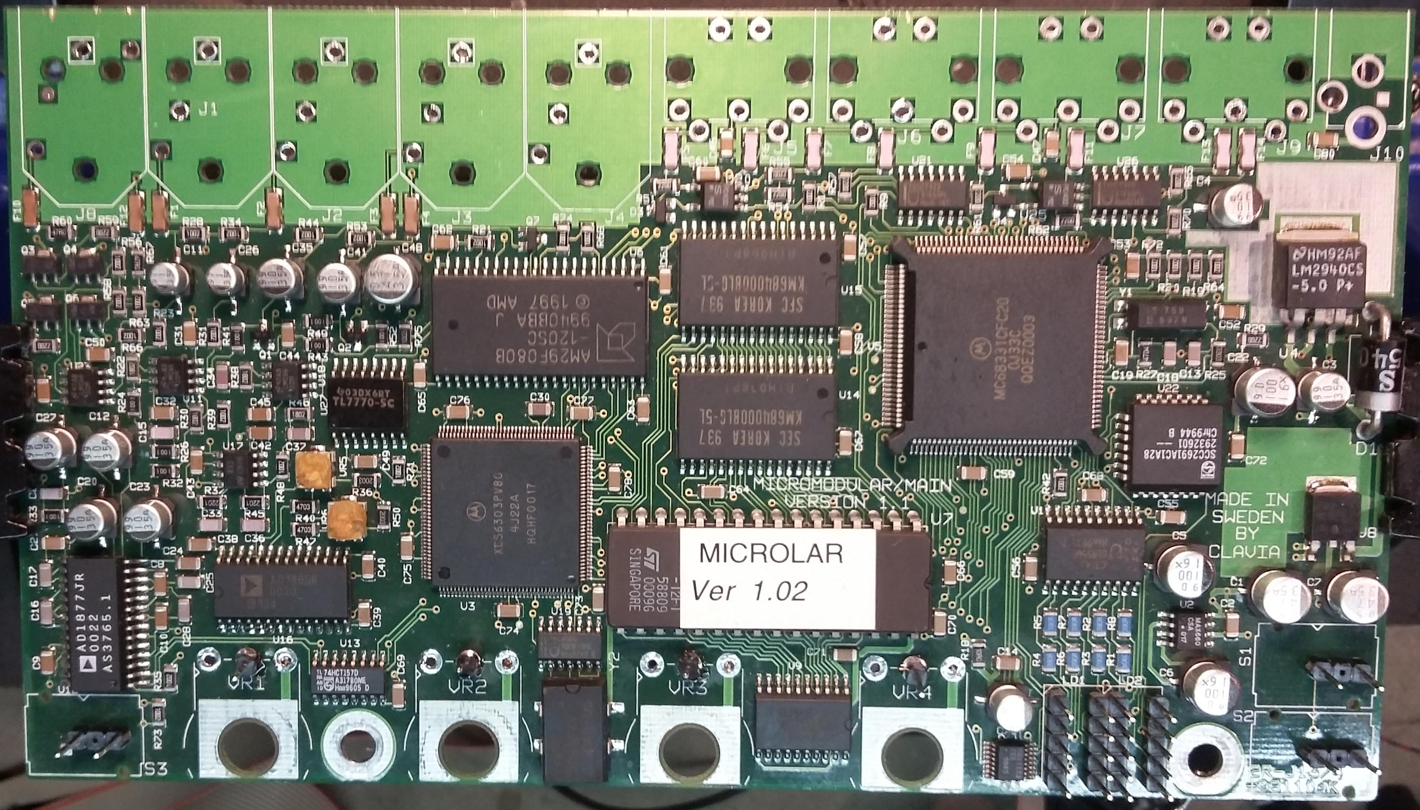
So! Let's dig in and start by removing all the controls and connectors!
With some careful work all required components were desoldered. The PCB holes are quite wide, so the pins are desoldered easily. I kept the PCB grounded at all times
to protect the circuitry for ESD discharge.
Trying out with several sizes of aluminum panels i had in the box, i came to a 16HP size as most suitable. Now a little puzzle to get everything in a logical position..
Now it got to a little puzzle on how to best place the components on a new face plate. To conform with Eurorack, the 6.3mm jacks will be replaced with 3.5 sockets (PJ3410 insulated type from
Thonk, UK).
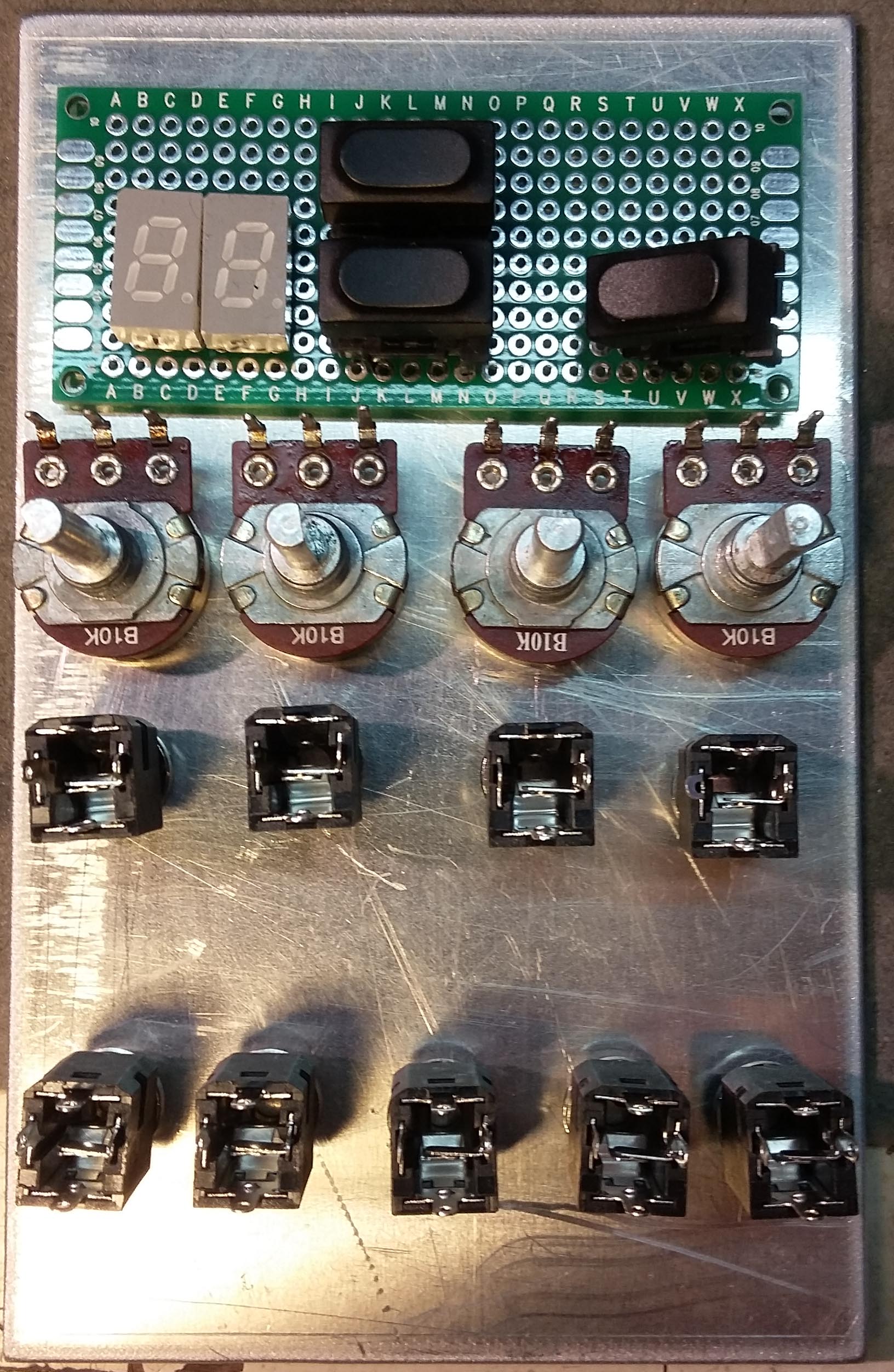
The original components are re-used and mounted to the new front plate by first mounting them on pieces of experiment PCB boards and then bolted to the front. I made these on the fly.
To mount the PCB i made an angled aluminum carrier plate that bolts with two bolts to the front plate. I had some nice and strong black finished M4 hex bolts that suited with the front design.
I chose not to integrate the four MIDI DIN sockets, but to have them on a temporary face plate. I can later switch them to the back of my case, or to replace them entirely with MIDI-over-USB.
A great IC would be the CH345 (available on AliExpress), that has dual MIDI. Ideal to be integrated here, already in house, but that will need some testing. The Micro Modular is quite picky with MIDI as there's a fairly high rate of communication needed to the host PC! Many USB to MIDI converters i tried fail to keep up and connection was lost.
 Puzzle |
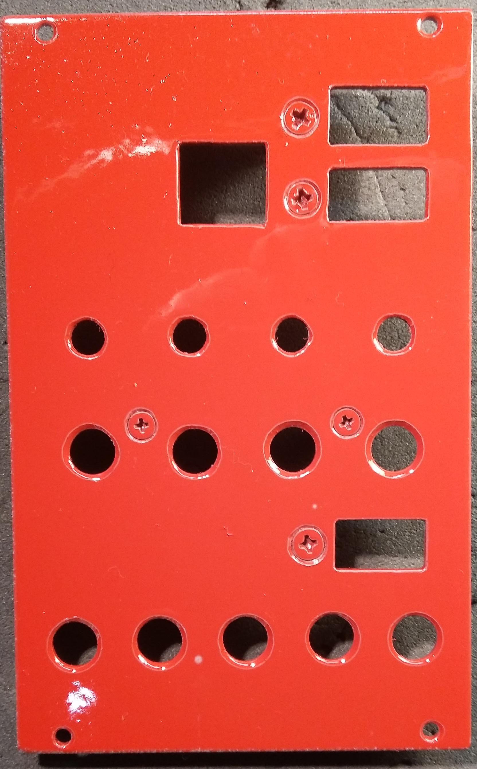 Gray primer and of course mandatory red final spray paint. |
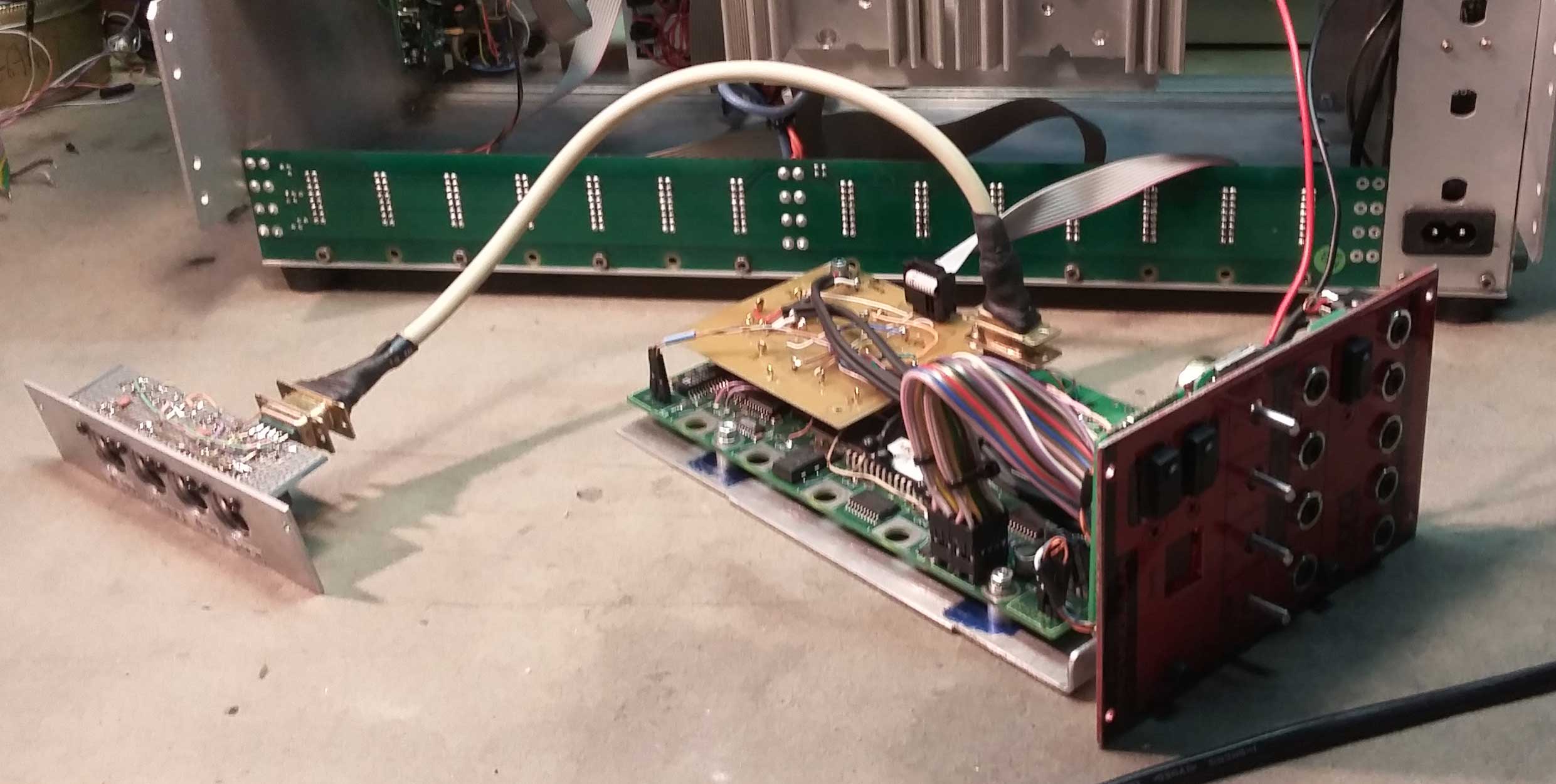
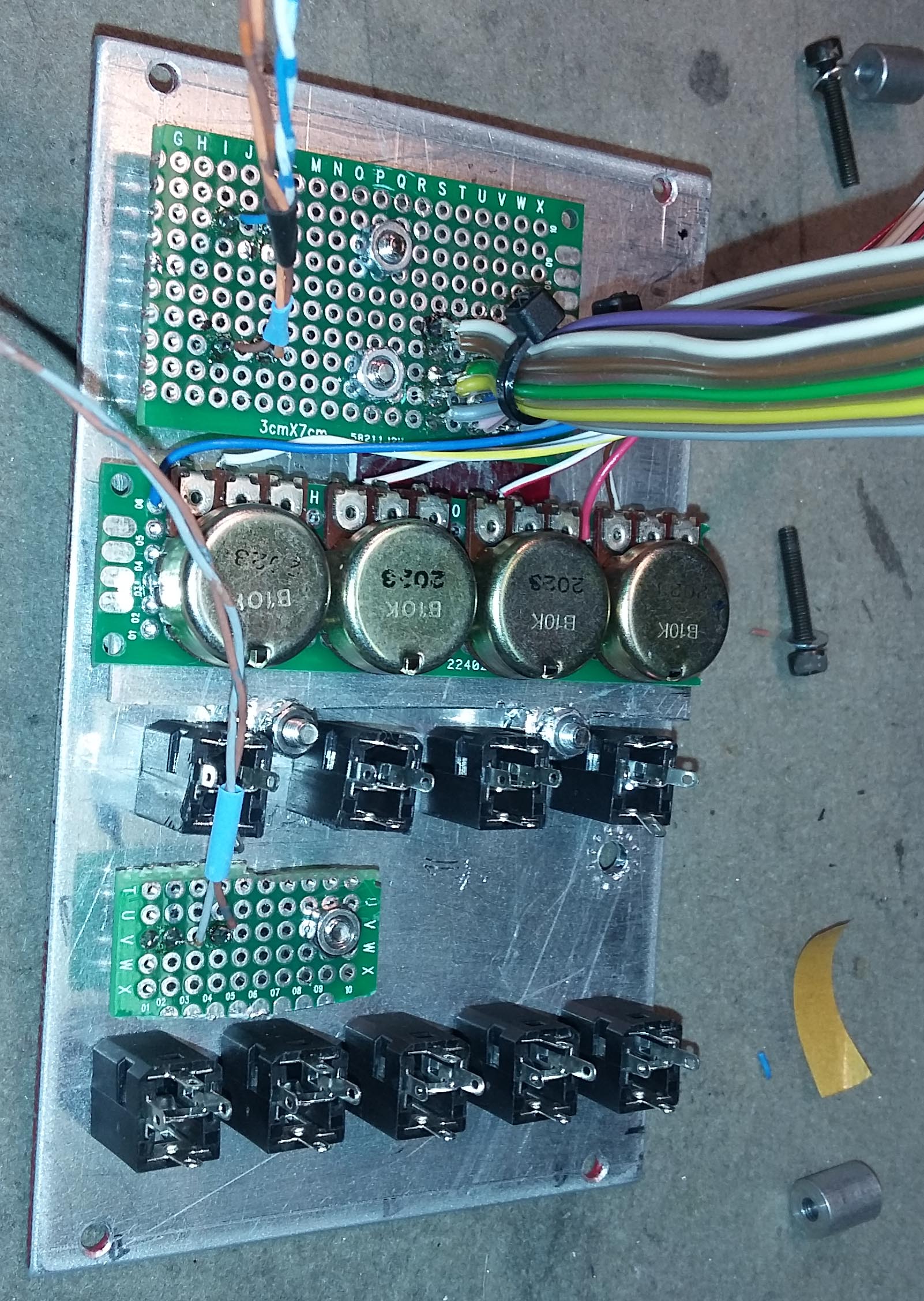 Trial mounting of the components. |
 |  |
As you might have noticed, there's four jack inputs with the potmeters. This is where things get interesting: The volume pot and the three parameter pots are CV controlled!
Control of the volume allows to act like a kind of VCA input. The output volume controlled by a CV from the modular system; like from an envelope or LFO.
The three parameter inputs allow control of parameters in a Micro Modular patch. And keeping in mind a single control can modify multiple parameters in a patch this makes for very interesting modulation possibilities!
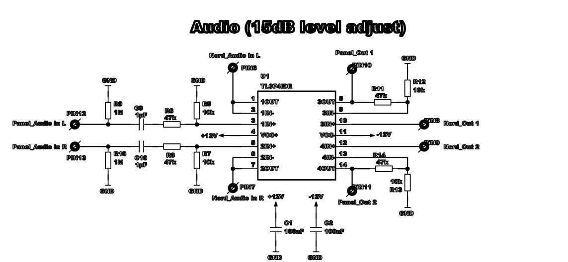
One little snag is that the signal levels used by the Micro Modular are a little different from levels generaly found in Eurorack modules. And a way has to be found to replace the potmeters with signal control inputs.
It called for a small PCB to be made to modify the signals.
This required some research. First, the audio in/outs of the Nord were measured to be about 1Vpp. In modular world it's more like 5-6Vpp. Which means that input signals should be attenuated by some 15dB and the outputs should be amplified bby 15dB. The headphone output is OK and is wired directly from the Nord PCB to the 3.5mm front socket.

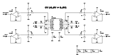
Full schematics and PCB design can be downloaded here (PDFs in ZIP).
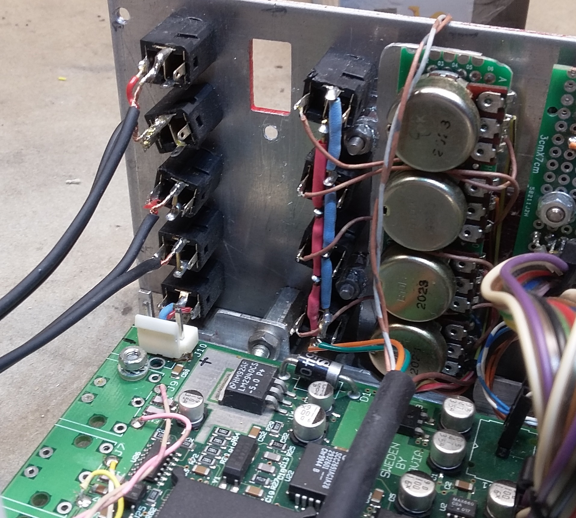
Like with most synthesizers, the Nord Micro Modular gets it supply from mains power. In this case via a 9V 500mA wall wart. Additionally, my signal adapter PCB needs +12V, -12V, +5V and -5V. And the +/-5V needs to be well controlled, as CV control is relative to these voltages.
In my Eurorack i use the standard Doepfer power back planes, with the well known -12V, GND, +12V, +5V, Key CV, Gate signals.
So there is no 9V available. And only +5V, but not that accurate. Time for some adaptations.
First, the main 9V supply. It could be derived from the +12V rail. The three pin 78xx family of regulators are fantastic for such a job and they are available for a large range of output voltages and can handle 1A, when properly cooled. In this case a 7809 could make +9V.Taking a measurement, the Nord draws about 400mA, which would also be drawn from the +12V. that would be quite a lot of power!
Having a close look at the Nord, first thing that happens is that the wall-wart voltage is reduced to 5V by a similar three pin regulator: LM2940C. It is an advanced, low drop linear regulator with an input range of 6-26V and a fixed 5V output. Sowww... 12V 400mA input (Is 12x0.4 = 4.8W) would have to be converted to 5V 400mA (5x0.4= 2W), which is a waste of energy and in my case it would use half the 1A rated current on my 12V rail. So i went for an approach using a switching power supply. Looking around on AliExpress and eBay, one can find these nifty little switching power supply boards. Mostly sold as supplies for Arduino or alike.
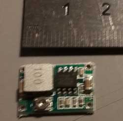
Switching mode power supply, SMPS
Here's one i had lying around; it's just about an euro a piece and can very efficiently down-regulate higher voltages to lower ones, while reducing input current. It's got a little trimmer for setting the required output voltage. I set the output voltage to 7V and hooked it up to the Nord. The LM2940C requires a minimum of 6V, but there is a diode reversal protection in series that causes an additional 0.6V voltage drop. Setting to 7V, the LM2940C receives some 6.4V, wich is ample to supply the system. On the 12V, current now is reduced to 0.24A, or 2.88W, which should be fine. Measuring before the 12V regulator in my rack, i even had +16V though and in the end i hooked the Nord with SMPS up to this raw supply and even reduced current to some 190mA.
The required +12 and -12V for the adapter PCB draws negligable power, so i hoked that up to the Doepfer rail. The +5V and -5V were derived from this with a simple OpAmp circuit, where i took the Nord 5V as a reference. All controls are relative to this 5V value. (It measured at about 5.08V)
Measurements later showed everything to work fine this way.
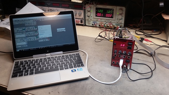
Ready for some testing!
A late night demo i did with the Nord Modular Modular installed in the rack can be found here on YouTube.
Adding USB MIDI It's now 2020. Over time i found that the use of the four DIN MIDI connectors was rather cumbersome. What i mostly -and most- needed was quick access via the graphic Clavia Nord Modular editor. Some time back i found a CH345 chip that could convert traditional MIDI to USB MIDI. I made a test PCB with this chip, but it worked poorly. Main thing was it just got stuck after transmitting a few bytes. Tried several chips from the batch, but all had similar behaviour.. bummer. Two years back while visiting the Superbooth in Berlin, i met a company Ploytec, who had a chip named GM2. It promised two full MIDI connections; with dedicated USB endpoints. They were readily available and last year in ordered some through USB-audio.com. I was a bit weary, because there's not too much documentation on the chip. With the Corona lockdown.. well, one goes through the cupboards.. i decided to give it a go and just make the circuit as published in the evaluation board schematic.
Making a PCB. I wanted to test things first, but i needed to make a PCB to handle the small SOIC-14 IC. With that in mind i first went over the racked Micromodular to find a spot where i could place the PCB/USB connector. And there really was just one spot left! The PCB had to be small. After a good deal of PCB compressing i finally got it small enough. Instead of the bulky DIN connectors, i have all four connections running through a single DB-9 connector, but the design is like the Ploytec evaluation board. Optocoupler details.
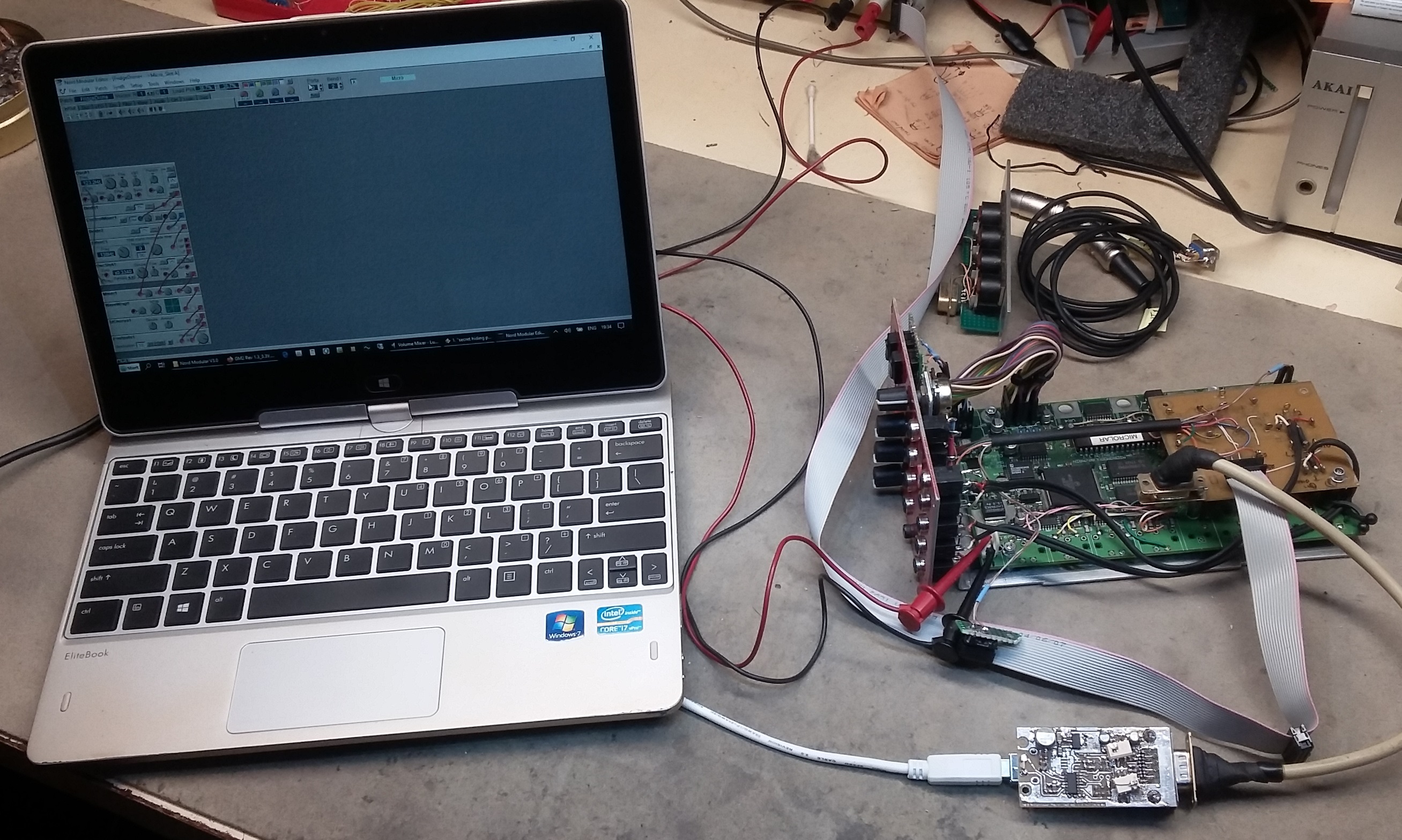
I did not have the CNY17 in stock, but i did have the Sharp PC123X that has similar specs as the CNY17. The PC123X is in a small DIP-4 housing, saving a bit of space on the PCB. Plugging things in; the ultimate test. And then quickly to the ultimate test! USB connection to the laptop.. bleep! bleep! Two USB interfaces showing up! Hooking it up to the Micromodular and:
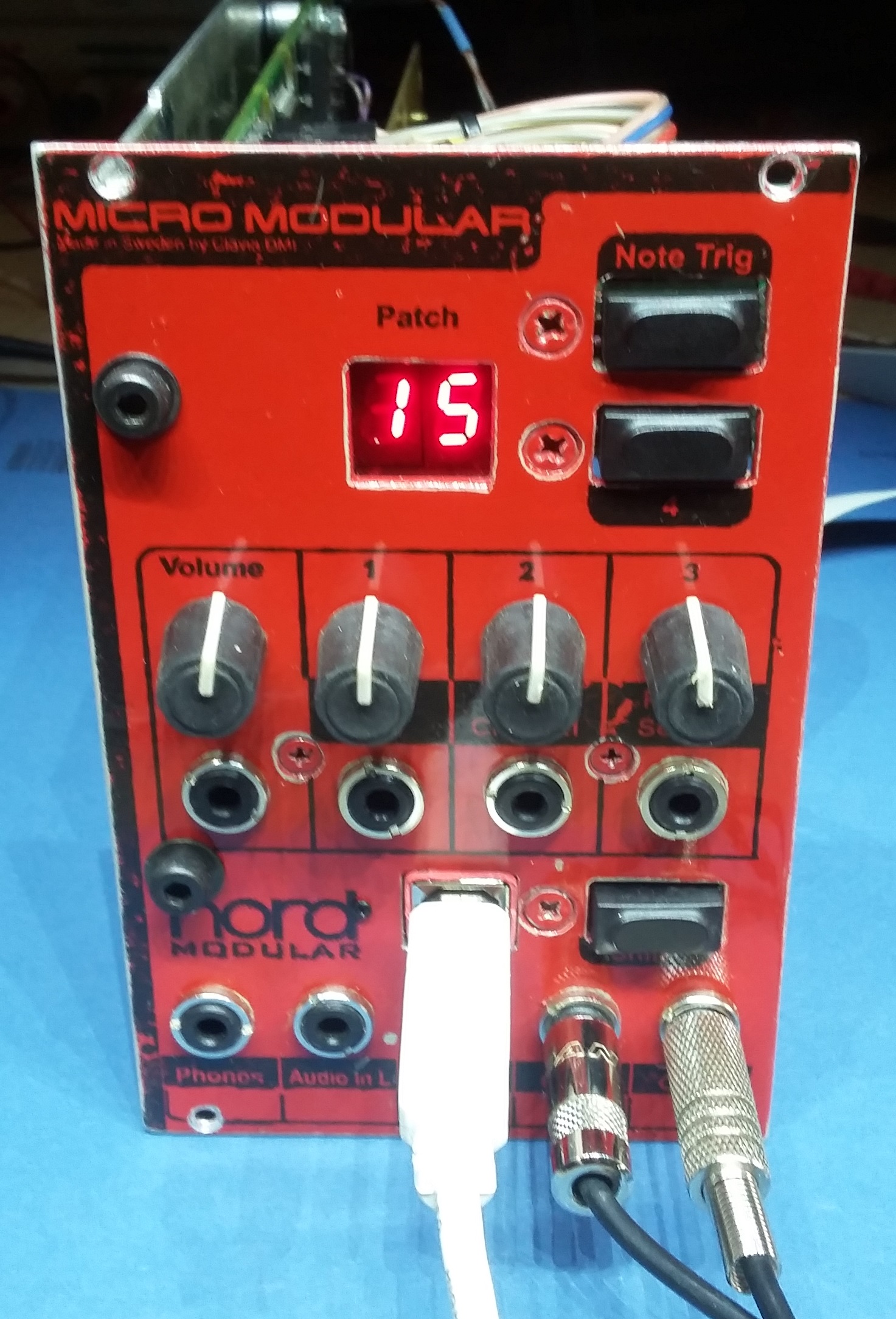
Yes, it worked! The Clavia software runs fine on my Windows 10 Home machine; just fire up the EXE. MIDI interface 2 connects directly to the synth (original 'PC in/out' midi connections) and the current patch is shown in the editor. Simulating a keyboard through MIDI-OX played the synth via interface 1 (original 'MIDI in/out' ports) and the port receives a stream of $F8 clocks from the synths coming in! Make sure only MID-OX events go out the port, or you get a mighty MIDI loop! Mounting the new USB interface Now for some tinkering. Finding the right spot to mount it, so it even looks decently. And then some hole making.. Yes, it takes a little effort to get good access and to properly layout what you are going to drill and might kill.. My two cents; draw everything and then step back for a little while. Here, at first i'd made layout lines that would have gone straight through my logo on the front. I got back from my coffee break during which this spung to mind and luckily could redo the layout!
Mod ready. And here's the USB MIDI mod finished!
<back to experiments main page
poesboes Initial date 18-03-2017, last edited 07-05-2020
Powered up for the first time! Running one of my droning patches. I had loaded them prior to the modification. (I.e. it is supposed to sound the way it does!)
Or.. nearly done..
There it should come... mmmm.. (click image for full size)
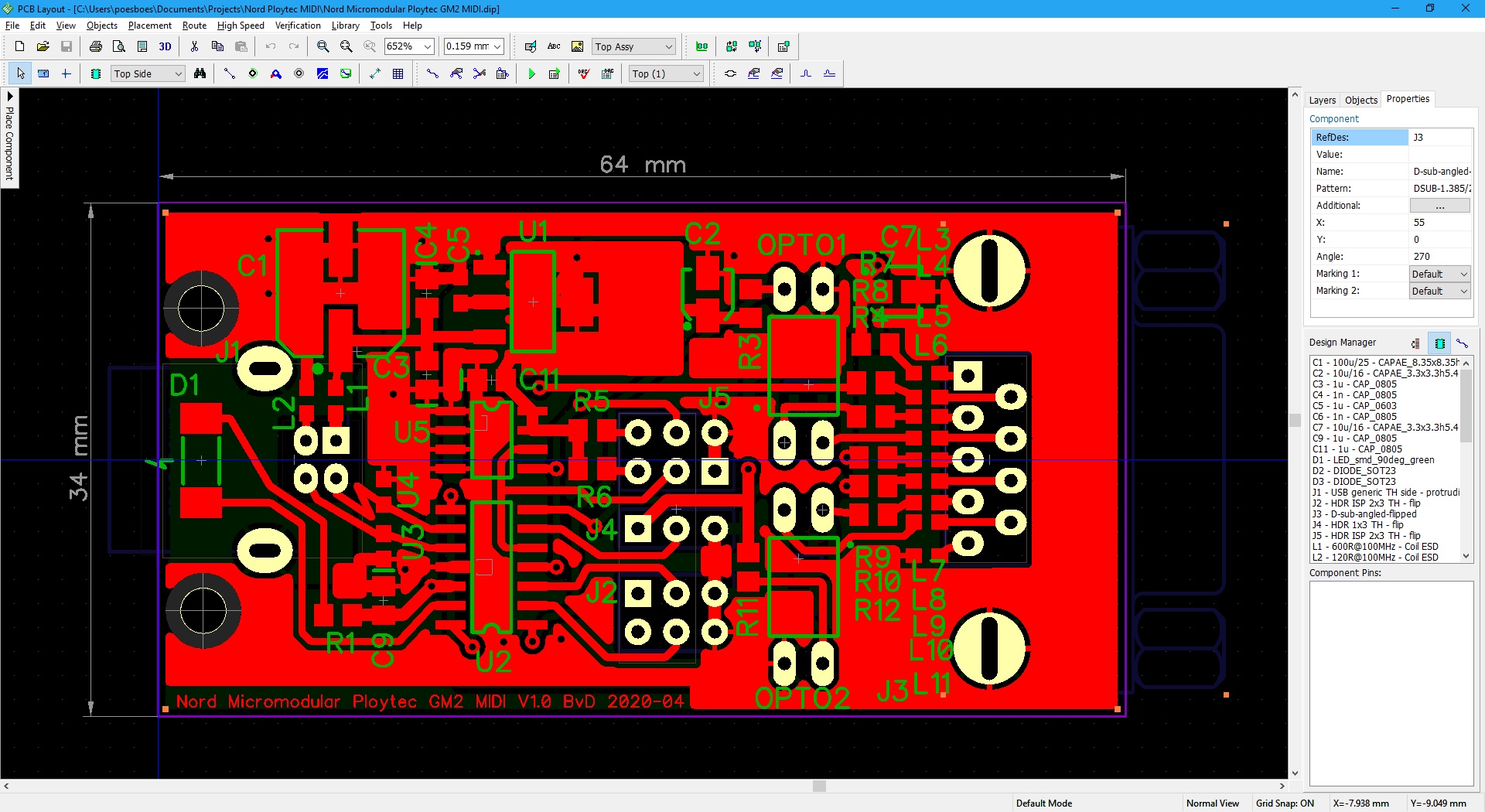
Finished PCB in DipTrace. (click image for full size)
Without the GM2 chip in place I did some tests to see if the optocoupler circuits worked. Simulating signals with a signal generator and checking with the oscilloscope. The signals looked terrible; faster transistions could hardly be seen. The optocouplers were far too slow for the MIDI signal rate!
Time for some research and looked on the web for details of MIDI. All specifications for MIDI can be found at the great MIDI Association website. Do check it out; you have to register if you want to download the manuals, but that's free and easy.
From the documents i found a specific note that MIDI calls for a maximum of 2us rise- and fall time of the optocouplers. The PC123X (and the CNY17 for that matter) are really too slow with rise- an fall times in the order of 20us.
I only had the very fast 10Mb/s 6N137 in stock and although it's rated for operation on 4.5-5.5V, tests showed it worked well at the provided 3.3V.
With a little wiggely pokery i managed to place the two 6N137 on the PCB in place of the PC123X's.
It works!
But in all... Thanks Ploytec for a such a fantastic and easy solution with the GM2 chip!
First have a look at the PCB. I mounted two small plastic spacers to enable panel mounting the PCB. The left piece doubled later to also mount the 'shift' button, to save some space and it could use the already present mounting hole. The right piece i screwed to the front panel with a tiny black screw as not to damage the Nord logo on the front.
A little extra care was given to the USB connector. As can be seen i shrouded it in some red shrink tube, to isolate it from the front panel. I don't want any ground connection from my computer to my modular system as it can induce a lot of noise! There is a ground connection via the DB-9 connector to the synth PCB, but i lifted the link between the USB ground and the synth ground and fitted a 10nF cap. This is a practice suggested by MIDI Associates; use a small cap.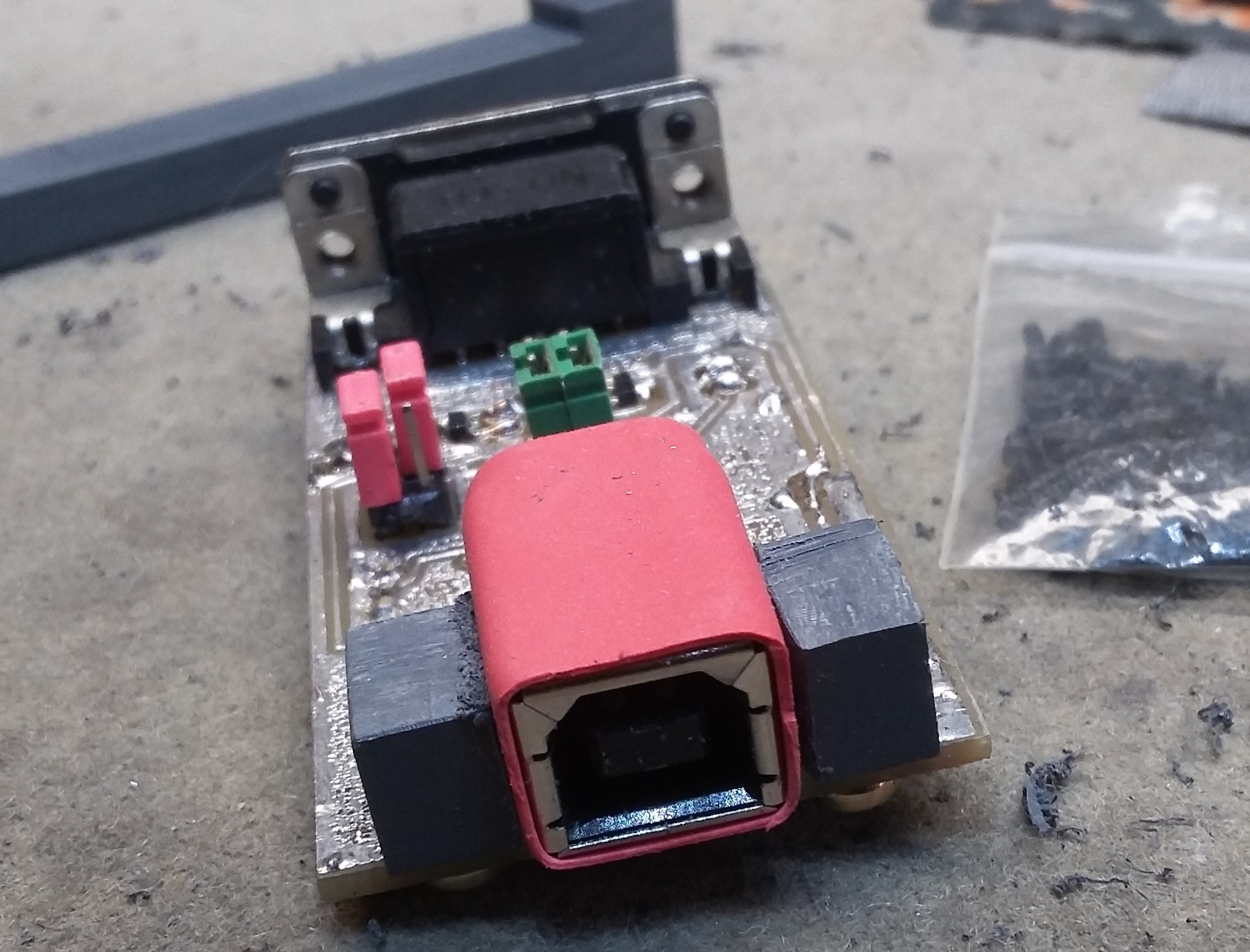
PCB seen on the front USB side.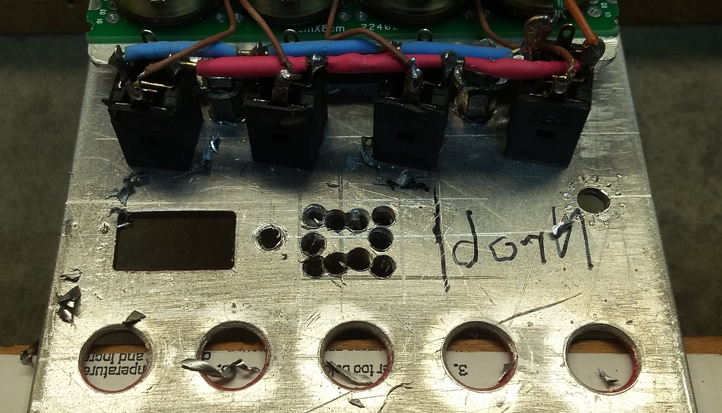
Pheeww.. just in time. I noted in mirror writing where the actual logo was and moved things to the left!
Doesn't looks too bad! Yeah, the art work.. later! ;)
And yes. Let's backup those patches; that's easy now.

Creative Commons Attribution-NonCommercial-ShareAlike 2.5 License